

Views: 221 Author: Site Editor Publish Time: 2026-02-28 Origin: Site


Content Menu
● The Structural Logic of Box Girder-to-Column Connections
>> Load Path Continuity and Stress Distribution
>> Why EVERCROSS BRIDGE Prioritizes Precision?
● Comparative Analysis of Connection Methods: Welding vs. Bolting
>> A. All-Welded Connections: The Peak of Structural Continuity
>> B. High-Strength Bolted Connections: Efficiency and Reliability
● Internal Architecture: The Role of Diaphragms and Stiffeners
● Advanced Seismic Engineering: The "Ductile Node" Concept
>> The EVERCROSS Standard for Seismic Safety
● Field Installation and Site Quality Control (SQC)
● Engineering the Future of Connectivity
● Frequently Asked and Questions regarding Steel Bridge Connections
>> 2. How do I decide whether to use a welded or a bolted connection for my bridge project?
>> 5. What are the standard testing methods to ensure the quality of a girder-to-column joint?
In the modern landscape of global infrastructure, the structural integrity of a bridge is only as strong as its weakest joint. At EVERCROSS BRIDGE, a premier Chinese manufacturer ranking among the top three in the industry, we understand that the intersection of a steel I-beam box girder and an I-beam column is the "heart" of the bridge’s load-bearing system.
This comprehensive guide delves into the technical nuances of connecting I-beam box girders to I-beam columns, exploring the mechanics, fabrication challenges, and innovative solutions that ensure a 100-year design life for highway and railway bridges.
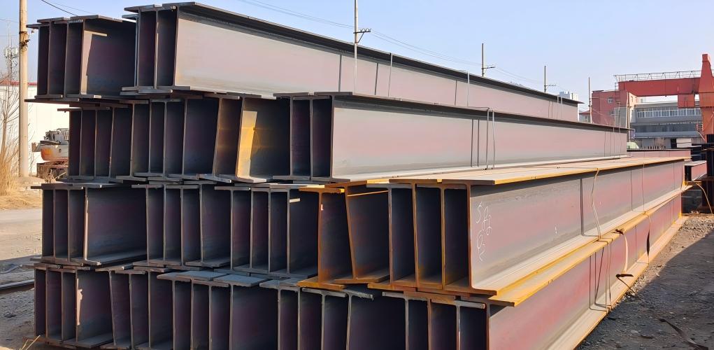
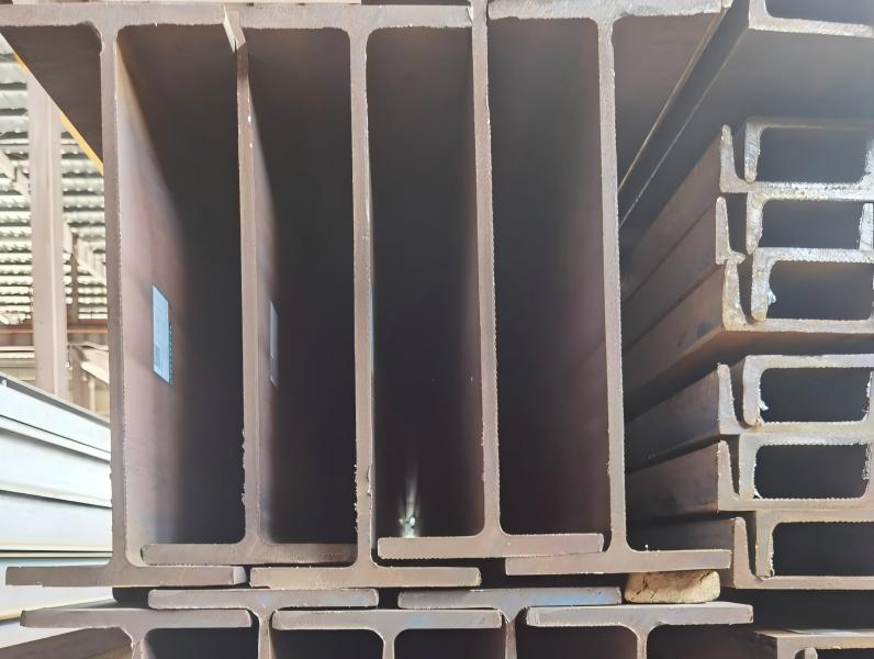
To understand how to connect these two components, one must first understand their individual roles. A steel I-beam box girder is chosen for its exceptional torsional rigidity—its ability to resist twisting forces caused by eccentric traffic loads or wind. Conversely, the I-beam column provides the vertical support, resisting massive axial compression and lateral forces from seismic activity or thermal expansion.
The connection serves as the primary gateway for load transfer. When a heavy train or a fleet of trucks crosses the bridge, the vertical load travels through the girder's web plates, into the connection node, and down through the column into the foundation.
●Moment Transfer: In a "rigid" or "moment" connection, the joint must be capable of transferring bending moments. This requires a seamless transition between the girder flanges and the column.
●Shear Resistance: The web plates of both the girder and the column must be reinforced at the connection point to prevent "web crippling" or shear buckling under extreme pressure.
●Torsional Management: Because box girders are closed sections and I-beams are open sections, the transition point creates a complex stress state that requires internal diaphragms to "close the loop" of the forces.
With our experience in projects like the Hong Kong-Zhuhai-Macao Bridge and various Belt and Road Initiative projects, we have seen that even a 2mm misalignment at this junction can lead to secondary stresses that reduce the bridge's fatigue life by decades. Our fabrication process utilizes high-precision CNC cutting and laser-guided alignment to ensure that every connection point is mathematically perfect.
The "Welded vs. Bolted" debate is central to bridge engineering. The choice depends on the project's location, the availability of skilled labor, and the environmental conditions during installation.
Welding is the preferred method for bridges requiring maximum stiffness and a sleek, streamlined appearance.
●Full-Penetration Groove Welds: These are used to connect the thick flanges of the box girder directly to the column or a transition cap plate. These welds ensure that the two components act as a single, monolithic piece of steel.
●Thermal Management: One of the greatest challenges in welding thick steel plates (often exceeding 50mm in mega-bridges) is managing the "Heat Affected Zone" (HAZ). If not cooled slowly and evenly, the steel can become brittle.
●Pros: Exceptional fatigue resistance, no risk of vibration-induced loosening, and superior aesthetics.
●Cons: Requires highly skilled certified welders and 100% Non-Destructive Testing (NDT) on-site, which can be weather-dependent.
In many international projects, particularly those managed by CCCC in remote regions, high-strength friction-grip (HSFG) bolts are the standard.
●Mechanism of Action: Unlike standard bolts, HSFG bolts do not rely on the bolt shank's shear strength. Instead, they are tightened to a specific tension that creates massive friction between the connected plates. The load is transferred through this friction.
●Splice Plates and Gussets: These plates "sandwich" the girder and column components, providing a redundant path for load transfer.
●Pros: Faster field assembly, easier quality control (using torque wrenches), and better performance in environments where on-site welding is difficult.
●Cons: Requires regular inspection for bolt tension and adds "bulk" to the connection's visual profile.
Technical Parameter | Welded Joint (Rigid) | Bolted Joint (Friction-Grip) |
Seismic Performance | Superior (with proper ductility design) | Good (allows minor energy dissipation) |
Installation Speed | Moderate to Slow | High |
Maintenance Need | Low (Corrosion focus) | Moderate (Tension check focus) |
Fatigue Resistance | High (Smooth stress flow) | Moderate (Stress concentrations at holes) |
A connection between an I-beam box girder and an I-beam column is not just an external affair. The real "magic" happens inside the box girder. At EVERCROSS BRIDGE, we specialize in the complex internal assembly required to make these joints stable.
Inside the box girder, exactly where it meets the column, we install a "Load-Bearing Diaphragm." This is a thick internal plate that acts as a bridge between the girder's side webs.
●Alignment: The diaphragm must be perfectly aligned with the column's flanges. If the alignment is off by even a few millimeters, the vertical load will "punch" through the bottom plate of the girder rather than being supported by the diaphragm.
●Manholes and Access: To allow for future inspection and maintenance, these diaphragms must have "manholes." However, cutting a hole in a load-bearing plate reduces its strength. Our engineers use Finite Element Analysis (FEA) to determine the optimal shape and reinforcement for these access ports.
To prevent the thin steel plates of the girder from buckling (the "oil-canning" effect), longitudinal and transverse stiffeners are welded to the interior surfaces. In the connection zone, these stiffeners are often doubled or thickened to handle the "Reaction Force" from the column. We use robotic welding arms to ensure these internal stiffeners have deep penetration welds, as they are often the first place where fatigue cracks appear in older bridges.
For bridges located in earthquake zones, the connection must be more than just strong—it must be "smart." Following the design philosophy used by CREC and PowerChina in seismic-heavy regions, we implement the Strong Column-Weak Beam principle.
In a massive earthquake, we want the bridge to survive even if it sustains some damage. To achieve this, the connection is designed to remain elastic, while specific "fuses" in the girder are allowed to yield.
●Reduced Beam Section (RBS): By strategically narrowing a small portion of the girder's flange near the column connection (the "Dogbone" design), we force any potential plastic deformation to happen there, away from the critical welds at the column face.
●Lateral Bracing: We provide additional lateral-torsional buckling resistance at the connection point, ensuring that as the bridge sways, the girder-to-column joint does not "roll" or twist out of alignment.
Every bridge component we produce for seismic zones undergoes simulated stress testing. By using high-ductility steel like Q355D or Q420qD, which can withstand significant deformation before fracturing, we provide an extra layer of safety for public infrastructure.
The final connection happens on-site, often under challenging weather conditions. A professional installation protocol is vital.
●Lifting and Positioning: Using heavy-duty cranes, the box girder is lowered onto the column. Temporary "locating pins" are used to guide the girder into the exact position.
●Environmental Monitoring: For welded connections, the temperature and humidity must be within strict limits. If it’s too cold, we use induction heating to pre-heat the steel to 100°C-150°C to prevent hydrogen cracking.
●Tensioning Bolted Joints: For bolted connections, we use a two-stage tightening process. The "Initial Snug-Tight" ensures the plates are in contact, followed by a "Final Tensioning" using calibrated hydraulic wrenches to reach the required k-factor (clamping force).
●Final Inspection (The Golden Rule): Every connection is inspected by a third-party auditor. We utilize:
Ultrasonic Testing (UT): To see inside the welds for any hidden pores or slag.
Magnetic Particle Inspection (MPI): To check for microscopic surface cracks.
The connection between a steel I-beam box girder and an I-beam column is a masterpiece of modern engineering. It represents the perfect balance of raw strength and mathematical precision. At EVERCROSS BRIDGE, our mission is to provide the global construction industry with the components that make these connections possible.
By combining our massive production capacity with the rigorous standards of China’s leading central enterprises, we ensure that every bridge we help build—whether it crosses a river in Southeast Asia or a mountain pass in Africa—is built to last.
This connection is the "focal point" of all structural forces. The box girder handles massive torsional and longitudinal loads, while the I-beam column manages vertical compression. The joint where they meet must facilitate a seamless "load path." If this connection is poorly designed or fabricated, it creates a stress bottleneck, leading to fatigue cracking or structural instability. High-precision engineering at this node ensures the bridge can withstand decades of heavy traffic and environmental stress.
The choice depends on three main factors: site conditions, required stiffness, and installation speed.
●Welded connections offer maximum rigidity and a cleaner look, making them ideal for urban bridges or spans where vibration must be strictly controlled. However, they require perfect weather and highly skilled labor on-site.
●Bolted connections (using high-strength friction-grip bolts) are preferred for rapid assembly and projects in remote areas or harsh climates. They are easier to inspect and replace but require more steel for the splice plates and gussets.
The internal diaphragm is a heavy-duty steel plate welded inside the box girder that aligns directly with the flanges of the I-beam column. Its primary job is to distribute the vertical reaction force from the column across the entire cross-section of the girder. Without a diaphragm, the thin bottom plate of the box girder would likely buckle or "punch through" under the concentrated pressure of the column. It also maintains the rectangular shape of the box girder, preventing torsional distortion.
In earthquake-prone regions, the goal is to prevent the bridge from collapsing by controlling where the damage occurs. We design the connection so that the column remains elastic (undamaged) while the girder is allowed to dissipate energy through "controlled yielding." This is often achieved by using a Reduced Beam Section (RBS) or "Dogbone" design, where the girder's flange is slightly narrowed near the connection. This ensures that if the bridge is overloaded, the girder bends safely away from the critical joint, keeping the main support structure intact.
At EVERCROSS BRIDGE, we utilize a multi-layered quality control protocol. For welded joints, Ultrasonic Testing (UT) is the gold standard for detecting internal flaws like slag inclusions or lack of fusion. Magnetic Particle Inspection (MPI) is used to find microscopic surface cracks. For bolted joints, we use calibrated hydraulic torque wrenches to ensure the Clamping Force meets the design specifications. Additionally, we often perform a factory trial assembly where the actual components are pre-fitted to ensure zero errors before they arrive at the construction site.


